
A Visual Studio 2013 demo project including all of the code in this article can be downloaded using the links in the resources section below.
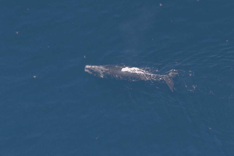
I was recently tasked with trying to isolate whales within an image of ocean water using C#. While building machine learning models, the question was raised: “Does ocean water add noise in a model to detect a specific whale while it is swimming in the ocean?” This was the primary question posed. However, before it could be studied, a method was needed to isolate various whales within many images of ocean water. Confused yet? Take a look at the following illustration…
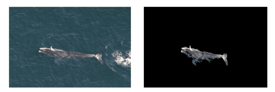
The whale may appear anywhere in the image of ocean water. Now, lets pretend you have literally have thousands of different images similar to the image on the left above. How can we create a second image containing only the whale as seen on the right? Doing this by hand in Photoshop was simply not an option. While I certainly do describe the algorithm I created to generate the image on the right above, the remainder of this article is less about creating the best possible whale isolation algorithm, and more about some of the C# image processing techniques I found along the way.
Aforge.Imaging
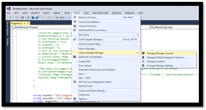
The first thing I began to look at was edge detection algorithms. The Aforge.Imaging [1] library for C# provides a ton of useful tools for working with images. Thanks to Nuget [2] in Visual Studio, the Aforge.Imaging library can be added to any C# project using one simple command from the Package Manager Console. The next image below illustrates how to open the package manager console from within Visual Studio.
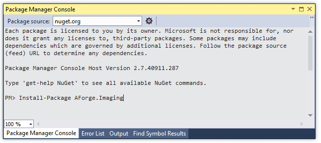
Once the package manager console is open, you simply type “Install-Package AForge.Imaging”. From this point, you are able to access the Aforge.Imaging objects via the “using AForge.Imaging” statement in C#. The next image shows using the “Install-Package AForge.Imaging” command from within the package manager console.
Edge Detection using Aforge
The imaging library provides four different edge detection algorithms (homogeneity, difference, sobel, and canny) [3] which are very easy to use. Unfortunately, these algorithms do not isolate whales as color images, only grayscale. While I believe they may be beneficial for developing many machine learning features, we were looking for a solution which generated color images.
However, I did learn a few tips when working with the edge detectors which are worth sharing. All of the edge detection algorithms within Aforge.Imaging accept black and white formatted images as input, 8 Bpp grayscale images to be specific. While this is noted in the documentation remarks [4], it was not obvious to me at first. The strange error messages did not really help either.
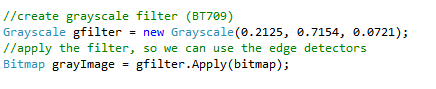
So, before using any of the edge detectors, I had to convert each image to grayscale. Fortunately, the imaging library provides a simple method to accomplish this task. The following code illustrates how to load a jpeg image as a bitmap and then convert it to grayscale:
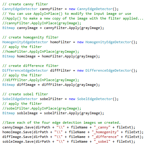
Once the image has been converted to grayscale, using the different edge detection filters is very simplistic. The following code illustrates using each of the four edge detection algorithms and saving each of the filtered images as bitmaps:
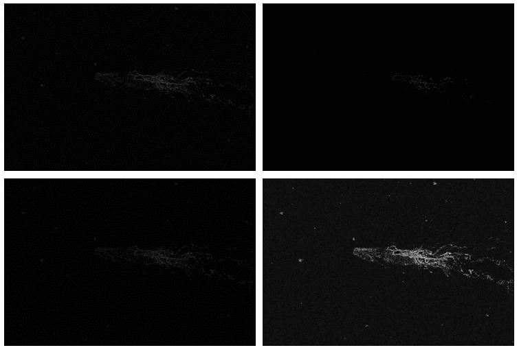
The results of the four different edge detection algorithms are shown below applied to a single image of a whale. You can see the slight variations in each of the images below. The variations become even more apparent, if you download the demo project and view the images at higher resolution. Also, notice how all of the resulting images are now entirely black and white:
Blob Processing using Aforge
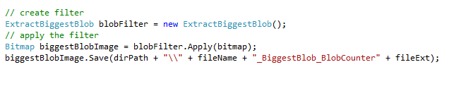
While in search of a more color oriented solution, I tried out the blob processing tool within Aforge.Imaging. This feature allows you to identify blobs within an image, count blobs, identify blob coordinates, filter blobs by size and many other useful features. The following code illustrates how to find and filter the biggest blob within an image:
Unfortunately, you can tell from the resulting image below that this technique does not work very well on isolating the whale from ocean water. The differences in color are too close between the whale and the ocean. To further complicate matters, the whale is partially submerged in the ocean water, so there does not seem to be a clear separation between the water and the whale. The following image shows what the largest blob looks like once it is extracted and saved as a new image. Suddenly it becomes very clear that the largest blob comprises almost the entire image with only a few smaller blobs missing here and there. Those “smaller” missing blobs are what appear as the gray specks in the image below.
Since I could not seem to isolate the whale using the tools provided in Aforge, I moved on to exploring other alternatives. Consider this fair warning that we are about to move into the land of pointers and “unsafe” code. The code becomes slightly more advanced for the remainder of this article.
Isolating RGBA Channels to Make a Custom Whale Filter
Just to explain the basics… Images (in the proper format) will contain a byte value (a number ranging from 0-255) for each Red, Green, Blue, and Alpha component of each pixel. These fours values determine the exact color displayed in that pixel. For simplicity sake, consider the Alpha value a measure of opacity (the condition of lacking transparency or translucence; opaqueness). There is a considerable amount of knowledge excluded from this description and outside the scope of this article. If you want to learn more, Google it. The goal here is to use RGBA values at the pixel level to see if we can craft a custom filter to target the whale.
While obtaining the RGBA values for each pixel within an image can be very cumbersome and performance inhibiting, there are two simple techniques you can use to dramatically speed up the code. First, why not resize your giant images? If you can get away with it, you will save a lot of processing time since the process is looping through each and every pixel. The following code illustrates resizing a jpeg image and converting it into a format in which the RGBA channels are accessible:
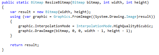
If memory serves me correctly, the code above was courtesy of a brilliant application for clustering similar images called the “Similar Images Finder” [5]. Various examples of RGBA isolation can be found in this project as well.
The second optimization technique is to use pointers via the “unsafe” keyword while processing pixel level data. WARNING: using the “unsafe” keyword in C# requires the special compiler directive “use unsafe code” to be checked. Your project will not build without checking this box when using the “unsafe” keyword which can be found on the “build” tab of the project properties window as shown in the image below:
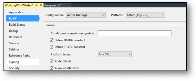
It is not the end of the world to use the “unsafe” keyword. This simply means, pointers can be very dangerous, use at your own risk, and make sure you understand the risks involved. The keyword is used to keep you safe by denoting only a small location within your code base in which pointers can be used. For more details see: [6].
Once you are all set up, you can now use the unsafe keyword to isolate the red, green, blue, and alpha values for each pixel in an image. The following C# code shows an example of how this is accomplished using pointers:
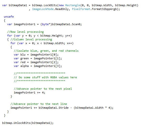
Simply put, the benefit of using pointers to read RGBA values from pixels is that the code is fast as hell. The code above illustrates using a nested for loop to process each pixel in an image row by row and column by column within each row. Since we are using pointers, you actually have to advance the pointer using the correct number of bytes. In this case, each value red, green, blue, and alpha value take up a single byte. Therefore, we advance the pointer += 4 bytes to move one pixel forward on the same row. Once we have looked at all the pixels on a single row, we have to consider the entire number of bytes in that row (represented by bitmapData1.Stride) and subtract the total number pixels / bytes we have already advanced the pointer for that particular row. We then advance the pointer by the difference to move on to the next row.
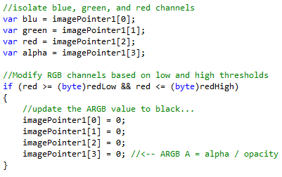
At any point during pixel processing, we are allowed to both read and write to individual pixel RGBA values. What I mean is that we can now create a custom whale filter that looks for pixels within certain color value ranges and then changes everything else to black! Now the question becomes, how can we figure out what the best color filter range is. After looking at many picture of whales, I determined that the biggest change in pixel values when moving from ocean water to whales seems to occur in the gray content of the pixel. This is reflected in the pixels red value and it’s saturation. Since we have direct, high performance access to the red value of each pixel, I devised a way to determine when the red value might move outside the ranges of red reflected in the pixels containing ocean water.
So, how do you know what the range of red values should be across the many different shades of ocean water reflected in multiple different pictures and varying times of the day you ask? Honestly, I had no clue. However, I did develop a reasonable heuristic which seems to produce nice results. The following code illustrates how the mode (most frequently occurring value) can be determined for only the first row of pixels. The logic here is that typically no whale pixels would be included on the first row of pixels. However, even if a small part of the whale was included, typically the mode of the red values should represent the most common value of red contained in ocean water pixels. If you do not believe this, you are welcome to take the performance hit and calculate the mode for red using all pixel values.
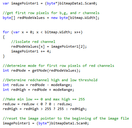
The code above determines the mode for all red pixel values in the first row. Once the red mode value for ocean water is determined, a small red threshold was set at 25 above and 25 below the mode value to act as the ocean water filter. After these thresholds are determined, we reset the image pointer to pixel 0 in order to apply the filter. When pixel processing begins we inspect each pixel’s red value to determine if it falls within the ocean water range. In the code below, when the pixel’s red value is determined to be ocean water, we change the pixel color to black.
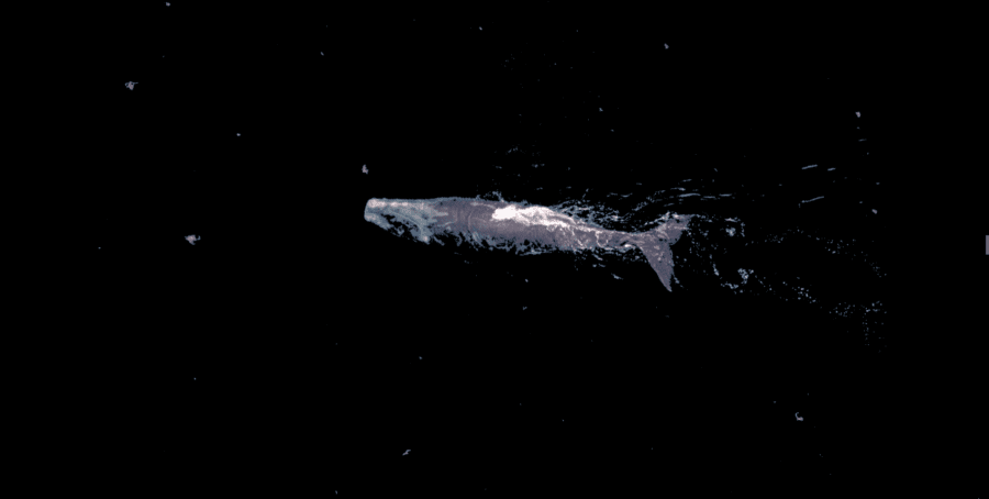
Finally, after the image filter is applied, we end up a step closer to filtering the whale with the best result so far. Notice that most of the ocean water has been removed. It is also interesting to point out that my own algorithm using custom RGBA channel filters seems to spot the same small blobs referred to as “gray specks” earlier when using the Aforge blob filter.
Perhaps now that we have a really nice contrast between the whale and the black pixels, we can use the blob filter from Aforge with some success to get rid of the smaller blobs. The code below shows the using BlobCounter object provided by the Aforge.Imaging library to find blobs in the image above.
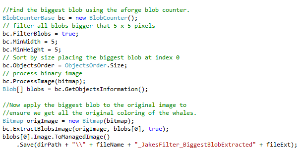
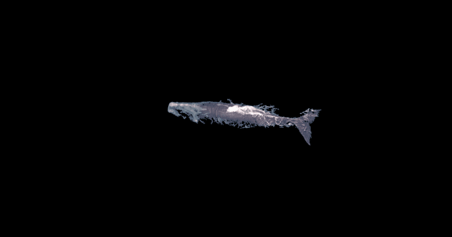
In the code sample above we use the Aforge BlobCounter object to identify all image blobs larger than 5 x 5 pixels in size. Next we sort each blob by size to determine the largest one. Once we have identified the largest blob, we can use the BlobCounter’s ExtractBlobsImage() method to extract only the largest blob from the original image (not the black image which the blobs are extracted from). The result is impressive! We have finally isolated a full color image of only the whale.
While the algorithm described above is not perfect, it does seem to work pretty “whale”! I tested this algorithm on around 11,000 images of whales downloaded from the Kaggle Right Whale Recognition Competition [7]. There are approximately 11,000 whale images there you can download and play around with. Perhaps you can improve the basic filter I created, or use the images it produces to develop machine learning features from and try out a submission on the Kaggle site. Please feel free to download the demo code using the link in the Resources section below.
Resources
- A Visual Studio 2013 demo project including all the code above and the complete custom whale filter can be downloaded here.
- Please feel free to learn more about me at www.jakemdrew.com.
References
- Aforge.NET, http://www.aforgenet.com/framework/features/, Accessed on 01/11/2016.
- Nuget.org, Aforge.Imaging, https://www.nuget.org/packages/AForge.Imaging/, Accessed on 01/11/2016.
- Aforge.NET – Edge Detectors, http://www.aforgenet.com/framework/features/edge_detectors_filters…., Accessed on 01/11/2016.
- Aforge.NET, HomogenityEdgeDetector Class,http://www.aforgenet.com/framework/docs/html/372f7aee-9ce1-a2a2-395…, Accessed on 01/11/2016.
- CodePlex, Similar Images Finder,https://similarimagesfinder.codeplex.com/, accessed on 06/24/2014.
- Microsoft, Unsafe Code and Pointers, https://msdn.microsoft.com/en-us/library/t2yzs44b.aspx, accessed on 06/24/2014.
- Kaggle, Right Whale Competition, https://www.kaggle.com/c/noaa-right-whale-recognition, accessed on 06/24/2014.