An unpublished experimental report may have an interesting new way to understand the unexpected result of the Michelson-Morley Experiment of 1887. The new understanding is embodied in a new theory the author calls “undulatory propagation.”
“Possible Detection of Ether Drift With Magnets (Not Light)”
This website reports an experiment that has apparently detected the absolute motion of earth through space. A moderate amount of reading is needed, but this report is not difficult to read. It does not contain mathematical gobbeldygook like that seen in many published articles. To get the most from this paper, however, it might be necessary for you to suspend belief in ideas that were taught to you as truth by well meaning, but misguided, teachers. Those ideas are the “hereditary prejudice” referred to by Einstein. This report should be of special interest to many students, teachers, and scientists, and of possible general interest to others.
BACKGROUND
![]() Every object in the observable universe appears to be in motion. The direction and speed of the sun’s motion are unknown, but the speed is likely to be very high. Our solar system as a whole is thought to move in one of the spiral arms of the milky way galaxy at a speed of 250 km per second (speeds are taken from sources such as www.sealevel.jpl.nasa.gov and www.thelivingmoon.com). This is about 560,000 miles per hour! The milky way moves relative to other nearby galaxies at a speed of 300 km per second (or about 670,000 miles per hour).
Every object in the observable universe appears to be in motion. The direction and speed of the sun’s motion are unknown, but the speed is likely to be very high. Our solar system as a whole is thought to move in one of the spiral arms of the milky way galaxy at a speed of 250 km per second (speeds are taken from sources such as www.sealevel.jpl.nasa.gov and www.thelivingmoon.com). This is about 560,000 miles per hour! The milky way moves relative to other nearby galaxies at a speed of 300 km per second (or about 670,000 miles per hour).
![]() To remain part of the solar system, all objects in the solar system must share the net solar motion. Objects in the solar system move relative to each other because they have their own individual motions in addition to the shared solar motion. A point on the surface of the earth revolves around the sun at about 30 km per second (67,000 miles per hour) and moves around the earth’s axis of rotation at about 0.47 km per second (1,051 miles per hour). It might seem strange to think that we humans on the surface of the earth might be rushing through space at a very high speed without feeling it. But the only time motion is felt is when it is changing, like when you are in an accelerating automobile. Relative motion, such as the apparent movement of the sun around the earth, can be very easy to detect, but can be misinterpreted.
To remain part of the solar system, all objects in the solar system must share the net solar motion. Objects in the solar system move relative to each other because they have their own individual motions in addition to the shared solar motion. A point on the surface of the earth revolves around the sun at about 30 km per second (67,000 miles per hour) and moves around the earth’s axis of rotation at about 0.47 km per second (1,051 miles per hour). It might seem strange to think that we humans on the surface of the earth might be rushing through space at a very high speed without feeling it. But the only time motion is felt is when it is changing, like when you are in an accelerating automobile. Relative motion, such as the apparent movement of the sun around the earth, can be very easy to detect, but can be misinterpreted.
![]() A little before the end of the 19th century, there was considerable scientific interest in measuring the net motion of the earth relative to a theoretical, stationary frame of reference in space. This motion was called the ether drift of the earth. It was thought a source of light could be used to establish a stationary point in space. Regardless of how a source of light might be moving, from the moment light is emitted, it propagates in all directions away from a stationary point in space. If the motion of the source of light could be detected relative to a point at which light had been emitted, that motion would be the absolute motion of the source.
A little before the end of the 19th century, there was considerable scientific interest in measuring the net motion of the earth relative to a theoretical, stationary frame of reference in space. This motion was called the ether drift of the earth. It was thought a source of light could be used to establish a stationary point in space. Regardless of how a source of light might be moving, from the moment light is emitted, it propagates in all directions away from a stationary point in space. If the motion of the source of light could be detected relative to a point at which light had been emitted, that motion would be the absolute motion of the source.
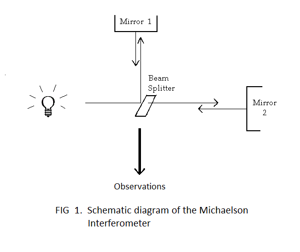
![]() One of the most famous efforts to detect the earth’s absolute motion was the Michelson-Morley Experiment of 1887. A special kind of mirror was used to split a single beam of light into two parts. The separate beams of light were directed along perpendicular paths to other mirrors, where they were reflected back. The reflected separate beams were re-combined to produce a pattern of alternating light and dark rings, the arcs on one side being called interference fringes. When the entire apparatus (called a Michelson interferometer) was rotated in a gravitationally horizontal plane, it was expected that ether drift would cause observable displacement of the interference fringes. The basic set up to produce interference fringes is illustrated by Figure 1. (This classic experiment deserves more of an account than is provided here. If you would like to read a more complete account, you are advised to consult a textbook in general physics or a website such as www.orgonelab.org/miller.htm).
One of the most famous efforts to detect the earth’s absolute motion was the Michelson-Morley Experiment of 1887. A special kind of mirror was used to split a single beam of light into two parts. The separate beams of light were directed along perpendicular paths to other mirrors, where they were reflected back. The reflected separate beams were re-combined to produce a pattern of alternating light and dark rings, the arcs on one side being called interference fringes. When the entire apparatus (called a Michelson interferometer) was rotated in a gravitationally horizontal plane, it was expected that ether drift would cause observable displacement of the interference fringes. The basic set up to produce interference fringes is illustrated by Figure 1. (This classic experiment deserves more of an account than is provided here. If you would like to read a more complete account, you are advised to consult a textbook in general physics or a website such as www.orgonelab.org/miller.htm).
![]() But it didn’t work as expected. No fringe shift was seen when the apparatus was rotated. When measured from a point fixed to the surface of the earth, the wavelength of emitted light was the SAME in all directions. This gives the impression the earth has no absolute motion. It was one of the most perplexing experimental outcomes in the history of science. Most scientists are unwilling to accept the idea the earth has no absolute motion. If there is absolute motion, as is generally believed, how could the wavelength of emitted light be the same in all directions? Though an answer to this question has been suggested and accepted by most scientists, the question itself remains a very important one. And it still needs a logical answer.
But it didn’t work as expected. No fringe shift was seen when the apparatus was rotated. When measured from a point fixed to the surface of the earth, the wavelength of emitted light was the SAME in all directions. This gives the impression the earth has no absolute motion. It was one of the most perplexing experimental outcomes in the history of science. Most scientists are unwilling to accept the idea the earth has no absolute motion. If there is absolute motion, as is generally believed, how could the wavelength of emitted light be the same in all directions? Though an answer to this question has been suggested and accepted by most scientists, the question itself remains a very important one. And it still needs a logical answer.
THEORY AND SET UP FOR MAGNETS
![]() The electromagnetic energy comprising a magnetic field propagates away from the source of the field just as light propagates away from the source of the light. The force exerted on a piece of iron, or on some other object sensitive to magnestism, depends on the strength of the field source and the distance the electromagnetic energy must propagate to reach the object. In the current experiment, the field source magnets are relatively powerful neodymium permanent magnets (NdFeB; Forcefield, Item # 0072, rated 12,100 Gauss). Much smaller neodymium magnets (Forcefield, D82-N52) were used in the detectors. The field source magnets are cylindrical and measure approximately 3.5 cm (1.5 in) in diameter and 2.5 cm (1 in) in height. The detector magnets are disk shaped, with a diameter of about 0.6 cm (0.25 in) and a thickness of about 0.3 cm (0.125 in). The detector magnet is positioned about 40 cm (about 16 inches) from each of two field source magnets, with the north pole of one source magnet facing toward the north pole of the detector magnet, and the south pole of the other field source magnet facing toward the south pole of the detector magnet.
The electromagnetic energy comprising a magnetic field propagates away from the source of the field just as light propagates away from the source of the light. The force exerted on a piece of iron, or on some other object sensitive to magnestism, depends on the strength of the field source and the distance the electromagnetic energy must propagate to reach the object. In the current experiment, the field source magnets are relatively powerful neodymium permanent magnets (NdFeB; Forcefield, Item # 0072, rated 12,100 Gauss). Much smaller neodymium magnets (Forcefield, D82-N52) were used in the detectors. The field source magnets are cylindrical and measure approximately 3.5 cm (1.5 in) in diameter and 2.5 cm (1 in) in height. The detector magnets are disk shaped, with a diameter of about 0.6 cm (0.25 in) and a thickness of about 0.3 cm (0.125 in). The detector magnet is positioned about 40 cm (about 16 inches) from each of two field source magnets, with the north pole of one source magnet facing toward the north pole of the detector magnet, and the south pole of the other field source magnet facing toward the south pole of the detector magnet.
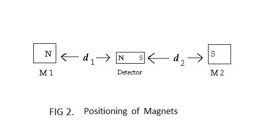
![]() The electromagnetic energy propagating from each of the source magnets exerts a repulsive force on the detector magnet, with the magnitude of each force depending on the distance the energy must propagate to reach the detector magnet. If the detector magnet has an absolute velocity toward one of the source magnets, the distance the energy propagates will be somewhat lessened by the motion, and the force of repulsion will be greater. The detector magnet would then have an absolute velocity away from the other source magnet, the distance the energy propagates will be somewhat increased by the motion, and the force of repulsion will be less.
The electromagnetic energy propagating from each of the source magnets exerts a repulsive force on the detector magnet, with the magnitude of each force depending on the distance the energy must propagate to reach the detector magnet. If the detector magnet has an absolute velocity toward one of the source magnets, the distance the energy propagates will be somewhat lessened by the motion, and the force of repulsion will be greater. The detector magnet would then have an absolute velocity away from the other source magnet, the distance the energy propagates will be somewhat increased by the motion, and the force of repulsion will be less.
![]() So that small changes in the repulsive forces would cause a visible change, the detector magnet was incorporated into a very sensitive detector assembly. The magnet was affixed to the end of a light weight, rigid plastic rod about 12 cm in length. A fine copper wire (24 ga) was attached to the plastic rod about 1.5 cm from the end to which the magnet was attached. A small aluminum rectangle (approximately 1 mm x 0.5mm x 0.1mm) was attached to the other end of the plastic rod to serve as a reflector of light. The copper wire was extended across the top of a small glass container so that the detector magnet was down in the container and the longer end of the rod extended upward from the container.
So that small changes in the repulsive forces would cause a visible change, the detector magnet was incorporated into a very sensitive detector assembly. The magnet was affixed to the end of a light weight, rigid plastic rod about 12 cm in length. A fine copper wire (24 ga) was attached to the plastic rod about 1.5 cm from the end to which the magnet was attached. A small aluminum rectangle (approximately 1 mm x 0.5mm x 0.1mm) was attached to the other end of the plastic rod to serve as a reflector of light. The copper wire was extended across the top of a small glass container so that the detector magnet was down in the container and the longer end of the rod extended upward from the container.
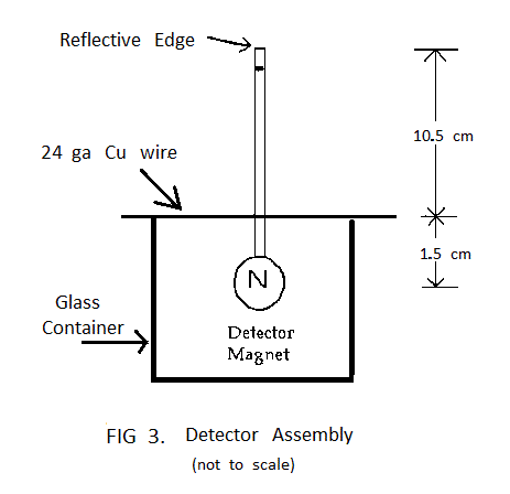
![]() As shown schematically in Figure 4, the detector assembly was positioned midway between two source magnets about 32 inches apart. Each source magnet exerted a repulsive force on the detector magnet. A small 12 VDC light and a measuring microscope (Edmund Scientific, Product H42-215, with a 2.4 mm eyepiece reticle calibrated in 0.02 mm increments) were positioned over the detector assembly, with the microscope being focused on the light-reflecting aluminum rectangle affixed to the longer end of the plastic rod. The microscopic view of this piece of aluminum will be referred to as the “detector image.”
As shown schematically in Figure 4, the detector assembly was positioned midway between two source magnets about 32 inches apart. Each source magnet exerted a repulsive force on the detector magnet. A small 12 VDC light and a measuring microscope (Edmund Scientific, Product H42-215, with a 2.4 mm eyepiece reticle calibrated in 0.02 mm increments) were positioned over the detector assembly, with the microscope being focused on the light-reflecting aluminum rectangle affixed to the longer end of the plastic rod. The microscopic view of this piece of aluminum will be referred to as the “detector image.”
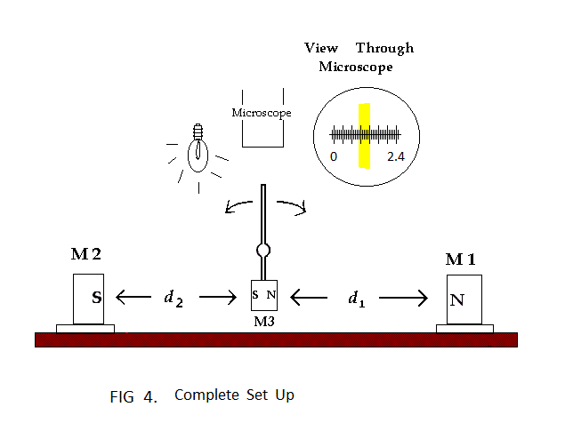
![]() One complete set up was positioned with the source magnets aligned on the east-west magnetic line of the earth. Directions in the earth’s magnetic field were determined with a sportsman’s compass. A second complete set up was positioned with the source magnets aligned on the north-south magnetic line of the earth. The microscopes provide inverted images, so directions reported in the recorded data are opposite to the actual directions below the microscopes. It was observed in both set ups that a small, manual displacement of either source magnet, either toward the detector magnet or away from it, caused a corresponding displacement of the detector image. After this observation was made, no magnet in either set up was manually displaced for any reason. Microscopes were positioned in the initial set ups so the detector image was near the center of the reticle measuring scale. As needed after the initial set up, the microscopes were moved slightly to ensure that any movement of the detector image would be along the reticle scale and not at some angle to the scale.
One complete set up was positioned with the source magnets aligned on the east-west magnetic line of the earth. Directions in the earth’s magnetic field were determined with a sportsman’s compass. A second complete set up was positioned with the source magnets aligned on the north-south magnetic line of the earth. The microscopes provide inverted images, so directions reported in the recorded data are opposite to the actual directions below the microscopes. It was observed in both set ups that a small, manual displacement of either source magnet, either toward the detector magnet or away from it, caused a corresponding displacement of the detector image. After this observation was made, no magnet in either set up was manually displaced for any reason. Microscopes were positioned in the initial set ups so the detector image was near the center of the reticle measuring scale. As needed after the initial set up, the microscopes were moved slightly to ensure that any movement of the detector image would be along the reticle scale and not at some angle to the scale.
![]() Both set ups were put into place near the end of December, 2012. Position of the detector image, however, was not recorded for several weeks. There was initially substantial instability in each set up, with the detector image swinging back and forth on the reticle scale by as much as plus or minus 0.15 mm at any given time. Apparently, small forces in the apparatus itself were responsible for this preliminary instability. These forces were mostly expended in a few weeks and recording of position data began in February, 2013, with only slight remaining instability. The values recorded in the data tables have an uncertainty of only plus or minus 0.02 mm in most cases, and 0.04 mm in a very few cases.
Both set ups were put into place near the end of December, 2012. Position of the detector image, however, was not recorded for several weeks. There was initially substantial instability in each set up, with the detector image swinging back and forth on the reticle scale by as much as plus or minus 0.15 mm at any given time. Apparently, small forces in the apparatus itself were responsible for this preliminary instability. These forces were mostly expended in a few weeks and recording of position data began in February, 2013, with only slight remaining instability. The values recorded in the data tables have an uncertainty of only plus or minus 0.02 mm in most cases, and 0.04 mm in a very few cases.
RESULTS
![]() The position of the detector image in each set up was observed and recorded on several days, and at several times of day, from mid February through early July, 2013. Including both set ups, a total of 138 positions were recorded. To view the position data, use either of the two links below:
The position of the detector image in each set up was observed and recorded on several days, and at several times of day, from mid February through early July, 2013. Including both set ups, a total of 138 positions were recorded. To view the position data, use either of the two links below:
![]() There was no significant movement of the detector image in the north-south set up. Small displacements did occur, but all such displacements were at random times. No pattern was ever established, and there was no repetition of position or movement on consecutive days. The earth’s rotation did not alter the orientation in space of the north-south magnetic field. The field source magnets exerted constant repulsive forces on the detector magnet, and the position of the detector magnet remained essentially constant over time.
There was no significant movement of the detector image in the north-south set up. Small displacements did occur, but all such displacements were at random times. No pattern was ever established, and there was no repetition of position or movement on consecutive days. The earth’s rotation did not alter the orientation in space of the north-south magnetic field. The field source magnets exerted constant repulsive forces on the detector magnet, and the position of the detector magnet remained essentially constant over time.
![]() The case was much different in the east-west set up. The detector image moved by as much as 0.38 mm in a 24-hour period (on 14 May). As illustrated in Table 3, movements, and to a slightly lesser extent positions, were well repeated on consecutive days.
The case was much different in the east-west set up. The detector image moved by as much as 0.38 mm in a 24-hour period (on 14 May). As illustrated in Table 3, movements, and to a slightly lesser extent positions, were well repeated on consecutive days.

For the set up with fixed terrestrial alignment on the east-west magnetic line of the earth, the earth’s rotation caused a full 360O rotation in space of the magnetic field once each day. Once each day, the slowly rotated source magnetic field was brought most nearly into alignment with the absolute velocity of the earth. The absolute motion of the detector magnet was then most nearly directed toward one of the source magnets, making the force of repulsion exerted by that magnet on the detector magnet a maximum. The detector magnet was pushed back and forth (slightly) as the forces exerted by the source magnets were increased and decreased by the rotation in space of the source magnetic field.
CONCLUSIONS
![]() The purpose of this experiment was to investigate the possible use of magnets to detect the absolute motion of the earth. It was found that cyclic variation in the strength of magnetic forces might reveal the ether drift of the earth. The magnetic drift detector in its simplest form, as described in this report, is low cost and easy to assemble. Further experimentation with the magnetic drift detector is recommended, especially with the drift detector being used in a room that is effectively shielded from external magnetic fields, to include the magnetic field of the earth itself. Calibration of the detector will enable measurement of the earth’s ether drift in celestial terms.
The purpose of this experiment was to investigate the possible use of magnets to detect the absolute motion of the earth. It was found that cyclic variation in the strength of magnetic forces might reveal the ether drift of the earth. The magnetic drift detector in its simplest form, as described in this report, is low cost and easy to assemble. Further experimentation with the magnetic drift detector is recommended, especially with the drift detector being used in a room that is effectively shielded from external magnetic fields, to include the magnetic field of the earth itself. Calibration of the detector will enable measurement of the earth’s ether drift in celestial terms.
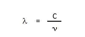
![]() Since the current experiment demonstrates that the absolute motion of the earth might be be magnetically detected, why do experiments with light not detect it? The important difference between optical detection and magnetic detection might arise from the reliance of conventional optical experiments on the wavelength of light. Magnetic detection of ether drift does not rely on wavelength. The wavelength of light is equal to the speed at which the light propagates divided by the frequency of the light:
Since the current experiment demonstrates that the absolute motion of the earth might be be magnetically detected, why do experiments with light not detect it? The important difference between optical detection and magnetic detection might arise from the reliance of conventional optical experiments on the wavelength of light. Magnetic detection of ether drift does not rely on wavelength. The wavelength of light is equal to the speed at which the light propagates divided by the frequency of the light:
![]() It was previously thought the speed at which emitted light propagates away from its source would depend on the angle between the absolute velocity of the source and the direction in which the light is emitted. For a light source moving with absolute velocity
It was previously thought the speed at which emitted light propagates away from its source would depend on the angle between the absolute velocity of the source and the direction in which the light is emitted. For a light source moving with absolute velocity![]() ” v “
” v “![]() the speed of light propagating at angle theta with the velocity is given by
the speed of light propagating at angle theta with the velocity is given by

It was also thought the frequency of light propagating away from a moving source at any angle theta would simply be the frequency of the source itself. If the speed of light propagation varies with the angle at which the light is emitted, but the frequency of the light is the same in all directions, the wavelength of the light must vary with the angle at which the light is propagating. This is the reason for expecting an observable fringe shift in the Michelson-Morley Experiment.
![]() But it is not necessarily true that the frequency of the light propagating in a given direction has to be the frequency of the source. As a wave propagates in a mechanical medium, phase is conserved. But this might not be true in the case of electromagnetic waves. Phase might change as the wave propagates. This new idea will be referred to as “undulatory propagation.” If phase does change as an electromagnetic wave propagates, the absolute motion of the source might affect the phase change so that the frequency of light emitted at angle theta with the absolute velocity would be given by
But it is not necessarily true that the frequency of the light propagating in a given direction has to be the frequency of the source. As a wave propagates in a mechanical medium, phase is conserved. But this might not be true in the case of electromagnetic waves. Phase might change as the wave propagates. This new idea will be referred to as “undulatory propagation.” If phase does change as an electromagnetic wave propagates, the absolute motion of the source might affect the phase change so that the frequency of light emitted at angle theta with the absolute velocity would be given by

The ratio of the speed of propagation and the frequency would than give the same wavelength at all angles, just as was seen in the Michelson-Morley Experiment.
![]() Since undulatory propagation is a relatively straightforward idea; since it is compatible with both magnetic detection of ether drift and the inability of conventional experiments with light to detect ether drift; and, since it does not require that “common sense” be ignored, it may be a desirable way to understand the outcome of the Michelson-Morley Experiment.
Since undulatory propagation is a relatively straightforward idea; since it is compatible with both magnetic detection of ether drift and the inability of conventional experiments with light to detect ether drift; and, since it does not require that “common sense” be ignored, it may be a desirable way to understand the outcome of the Michelson-Morley Experiment.
![]() Is undulatory propagation of electromagnetic waves “true”? This question might never be answerable with a confident “yes” or “no.”
Is undulatory propagation of electromagnetic waves “true”? This question might never be answerable with a confident “yes” or “no.” It would significantly add to the recognized distinctions between electromagnetic waves and mechanical waves. A scientific theory is simply an idea made up in an effort to understand or explain a given set of experimentally observed facts. There are always alternative possible ways to understand any given set of observed facts. The most that should
![]() ever
ever![]() be said, even after an idea seems to be supported by a broad range of observed facts, is that the idea is “probably true.” So … is undulatory propagation true? The most that can be said at this time is … “perhaps true.” Additional experiments should be done throughout the year as described in this report. This would confirm that the peak effect occurs in late spring only. If possible, a magnetic detector as described in this report should be set up in a room shielded from external magnetic fields, including the magnetic field of the earth itself. If these experiments confirm detection of ether drift, they would allow a reasonable person to suggest that the idea of undulatory propagation is “probably true” to account for the result of the Michelson-Morley Experiment.
be said, even after an idea seems to be supported by a broad range of observed facts, is that the idea is “probably true.” So … is undulatory propagation true? The most that can be said at this time is … “perhaps true.” Additional experiments should be done throughout the year as described in this report. This would confirm that the peak effect occurs in late spring only. If possible, a magnetic detector as described in this report should be set up in a room shielded from external magnetic fields, including the magnetic field of the earth itself. If these experiments confirm detection of ether drift, they would allow a reasonable person to suggest that the idea of undulatory propagation is “probably true” to account for the result of the Michelson-Morley Experiment.
Originally posted here
